| delorie.com/electronics/rx/rx62n-breakout.html | search |
| Actual Size (100dpi, click to zoom) |
|---|
|
|
Support for this project is via community volunteers at the Renesas Rulz web site. I'm not making a lot of money on these, so don't expect much personal service.
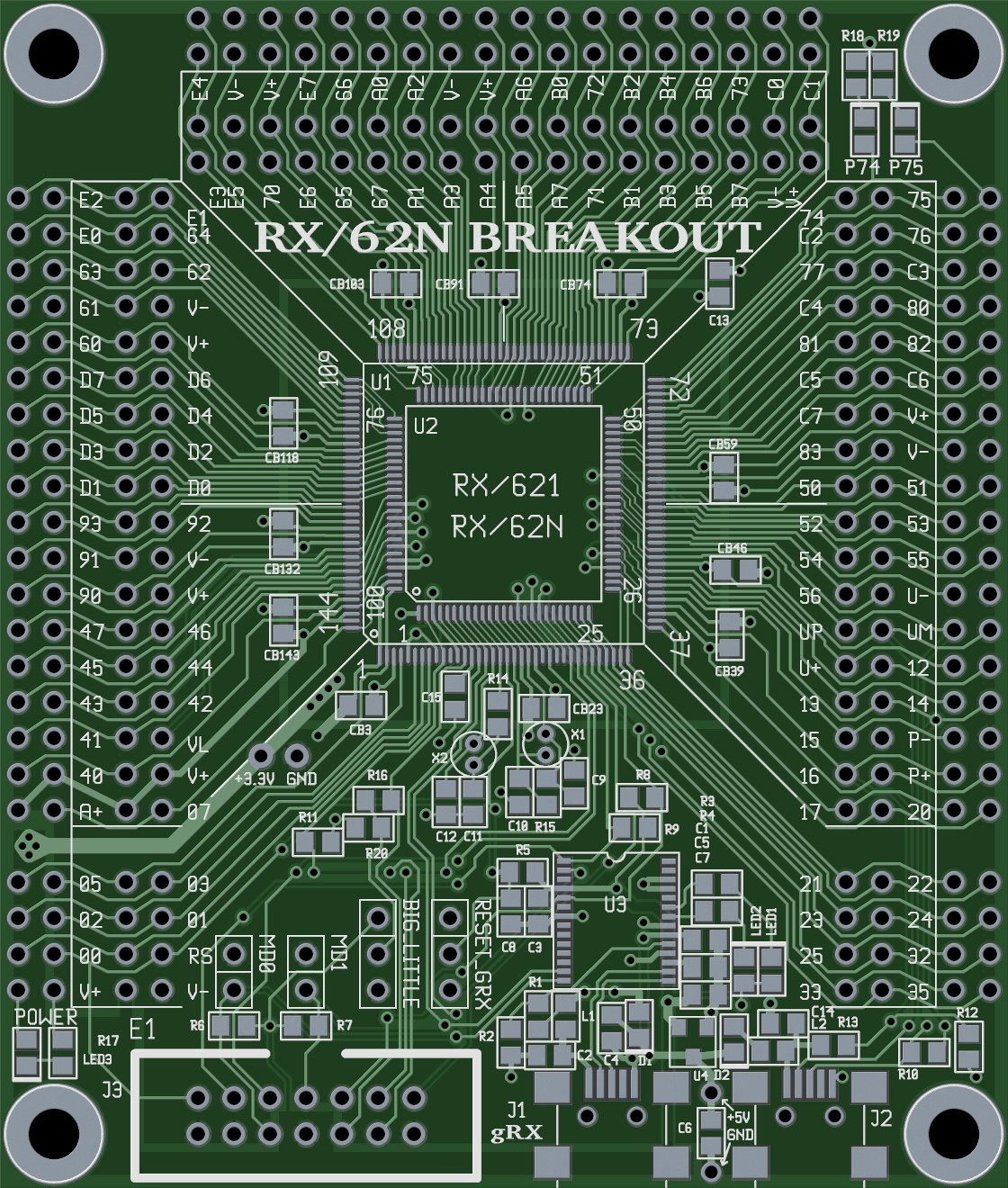
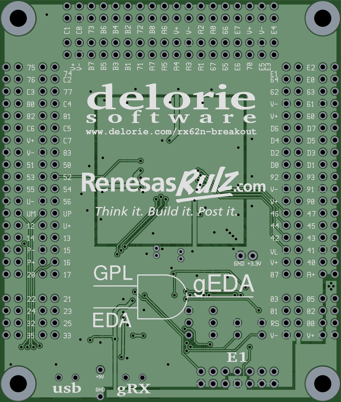
The design of this board was done using The gEDA Suite for both schematic capture and board layout.
The fab for this run was Sierra Proto Express via their No-Touch service.
The ordering option here is for a BLANK PCB. Cost is US$ 6.25 per blank pcb ($100/16 appealed to my inner geek). If you order just one, I'm going to stick it in an envelope taped to your invoice. 2-10 ships in a padded envelope. More than that gets a flat rate box. International: I've been having trouble with international, so if you don't get it after two weeks, email me. All payments are via PayPal, but they do let you use a credit card.
|
| ||||||||||
| Cables | Power | Parts Populated | OS | Notes | ||||||
|---|---|---|---|---|---|---|---|---|---|---|
| E1 | gRX | USB | E1 | JP | gRX | LDO | USB | |||
| Y | N | O | E1 | Y | O | N | N | O |
|
Power, programming, debug all from E1. Optional power from other source via headers. |
| Y | N | Y | USB | Y | O | N | Y | Y |
|
Power from USB, programming, debug from E1 |
| O | N | Y | USB | O | Y | N | Y | Y |
|
Power from USB, programming over USB via FDT or rxusb; manual jumper/reset |
| N | Y | Y | USB | O | Y | Y | Y | Y |
|
Power from USB, programming over USB via FDT or rxusb; manual jumper/reset, serial console via terminal emulator |
| N | Y | N | gRX | O | R | Y | Y | O |
|
Must install at least the RESET_GRX header, set for GRX. Program via gRX protocol (serial), serial console. |
| N | Y | Y | gRX | O | R | Y | Y | Y |
|
Must install at least the RESET_GRX header, set for GRX. Program via USB protocol under gRX control, serial console. |
Notes:
JP = configuraton jumpers (MD0, MD1, RESET_GRX, BIG_LITTLE)
gRX = FT232R chip (U3) and related circuitry, see schematics
LDO = 3.3v low-dropout regulator (U4) and related circuitry
USB = RX device USB and related circuitry
O = optional, R = at least RESET_GRX installed
If you've never hand-soldered fine-pitch QFP parts before, here's how I do it:
Soldering the 0603/0805 parts is similar - pre-solder one pad, hold part in place while reheating the solder, solder the other pad.
Note: After assembly, remove excess "no clean" flux from around the RTC circuit (xtal, caps, RX pins) and the USB pins (gRX, FT232R, USB, and RX pins). Some no-clean fluxes conduct slightly, which might corrupt these signals.
|
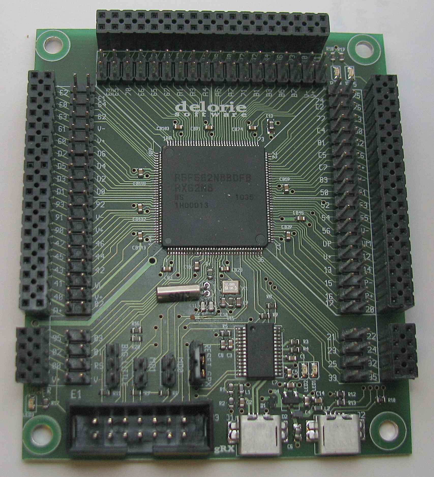
This is what the original prototype looks like assembled. Note that I chose to put female headers on the outer ring, and male headers on the inner ring. I use the male headers with my logic analyzer and the female headers with my solderless breadboards, but of course either row could be populated with any type of connector. |
|
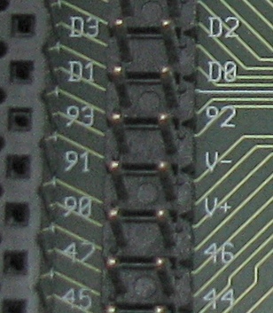
The inner ring has the port numbers next to each pin. In this example, you see Port PD.0 through PD.3, P9.0 through P9.3, P4.4 through P4.7, and Vdd (V+) and ground (V-). The port numbers are the same for the 144 and 100 pin devices, but the alternate functionality varies. |
| webmaster | delorie software privacy |
| Copyright © 2015 | Updated Jun 2015 |