| delorie.com/electronics/rx/ogg-mod.html | search |
| |
|
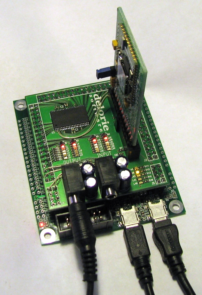
The OGG/DSP Module and demo software adds audio I/O (via ADC/DAC), fast SRAM (512 KBytes), and wifi (via the Redpine Wifi board) to the RX/62N Breakout board.
It was designed specifically to experiment with OGG encoding and decoding, which requires more memory than the RX chip itself contains. However, there's nothing ogg-specific in the hardware, it could be used for MP3 or DSP software as well.The first rev of the board was a rush job for me, and there were a number of wires needed to make it all work. The current rev has all the corrections, as well as moving the audio connectors so that the E1 can be used at the same time as the audio connectors.
The RAM chip of choice is the IS61WV25616BLL-10TL - an 8ns (at 3.3v) 256kx16 SRAM chip (Digikey 706-1105-ND). The RAM is on CS7b, mapped from 0x0100_0000 to 0x0107_FFFF. If the RX were a few nanoseconds faster, this RAM could run with no waits or delays at all. Even so, it can do a read in two cycles and a write in three, compared to five cycles for the fastest SDRAM.
| Chip Select | CS7-B |
| Address | 0x0100_0000 - 0x0107_FFFF |
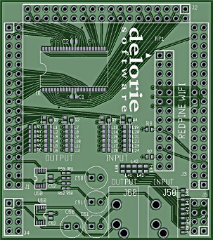
The audio input is buffered through two large capacitors to bias the "idle" voltage at half the ADC value, then buffered by a unity-gain op amp. The result is fed into AD0 and AD1 of the 12-bit ADC. Up to 3.3V peak to peak is accepted.
The audio output is connected to the two DAC outputs, buffered through a unity gain amplifier and two large capacitors, to give a 3.3V peak to peak audio output signal. Both inputs and outputs are full stereo and able to sample at over 44,100 samples per second.
There are two stereo bar graphs made of six LEDs each, in a six by four matrix, which are independent of the audio electronics but intended to be used to display the audio signal levels. The LED signals are all active high.
| ADC | AN0,AN1 |
| DAC | DA0,DA1 |
| LED columns | P4.2 - P4.7 |
| LED rows | P9.0 - P9.4 |
The module includes a connector for a Redpine Wifi companion card. Note: the Redpine board needs a beefier power supply than the breakout board has, so either (1) never "turn off" the card since turning it "on" will brown out the RX chip and reset it, (2) add about 900uF or more of capacitance to the breakout board, or (3) remove some of the post-switch bulk capacitance on the Redpine board.
| SPI | MOSIA-A, MISOA-A, RSPCKA-A |
| UART | TXD6-B, RXD6-B |
| CS | PC.4 (SSLA0-A) |
| RESET | P5.4 |
| IRQ | P1.5 (IRQ5-B) |
| GPIO1 | P1.7 |
| GPIO2 | P2.0 |
The Redpine software is included with the hardware module.
There are five additional LEDs on the module for generic status. A logic high turns the LED on.
| L40 | P2.5 |
| L41 | P2.4 |
| L42 | P2.3 |
| L43 | P2.2 |
| L44 | P2.1 |
| webmaster | delorie software privacy |
| Copyright © 2011 | Updated Dec 2011 |